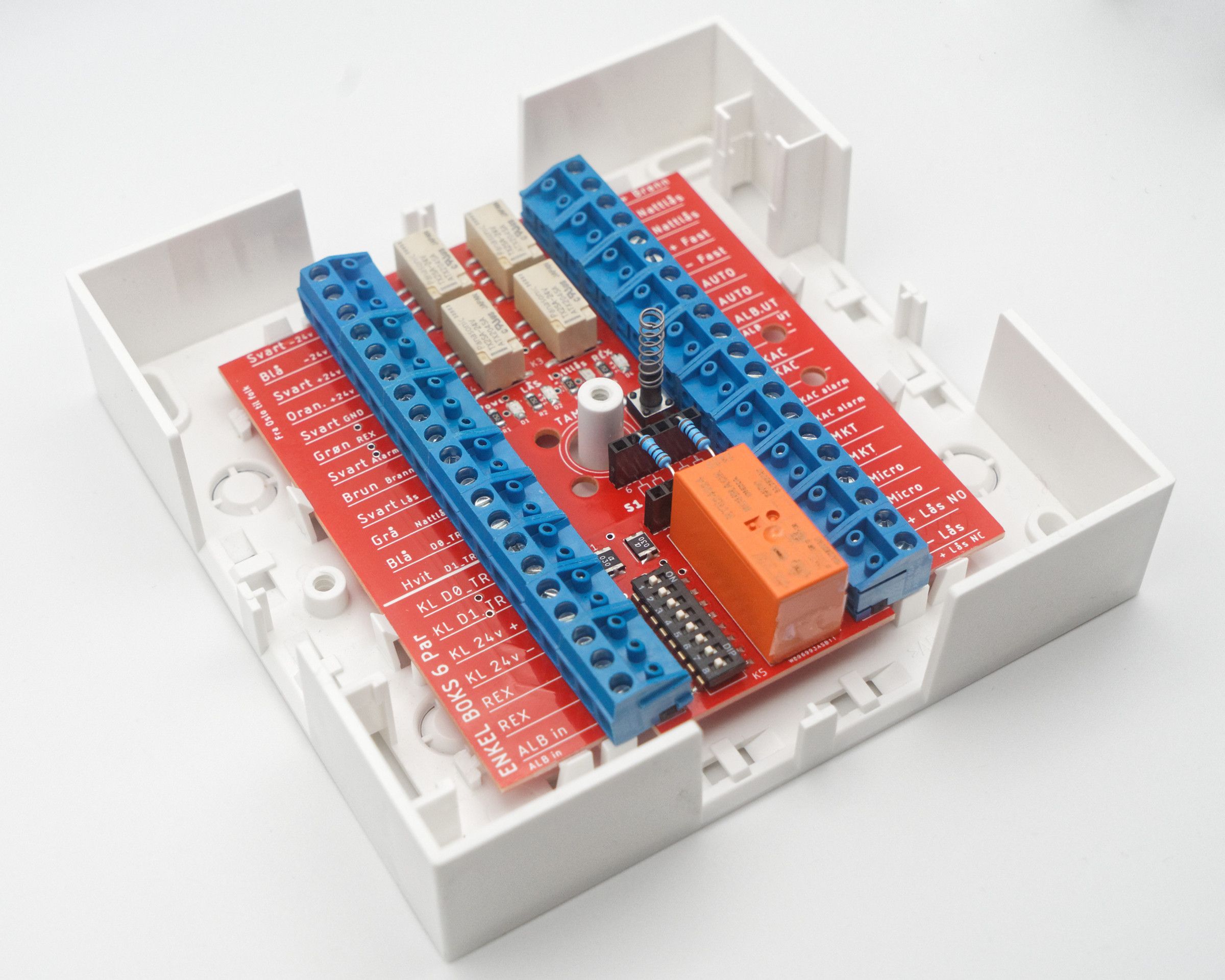
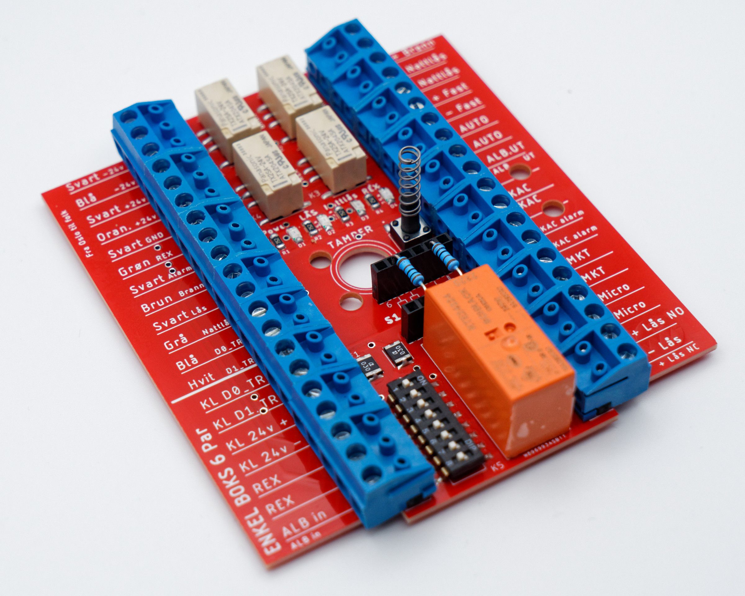
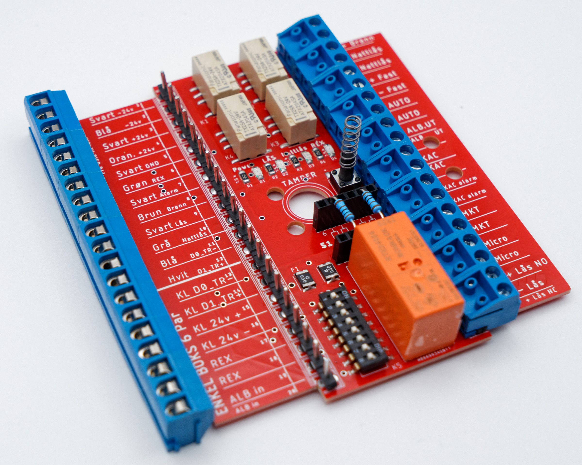
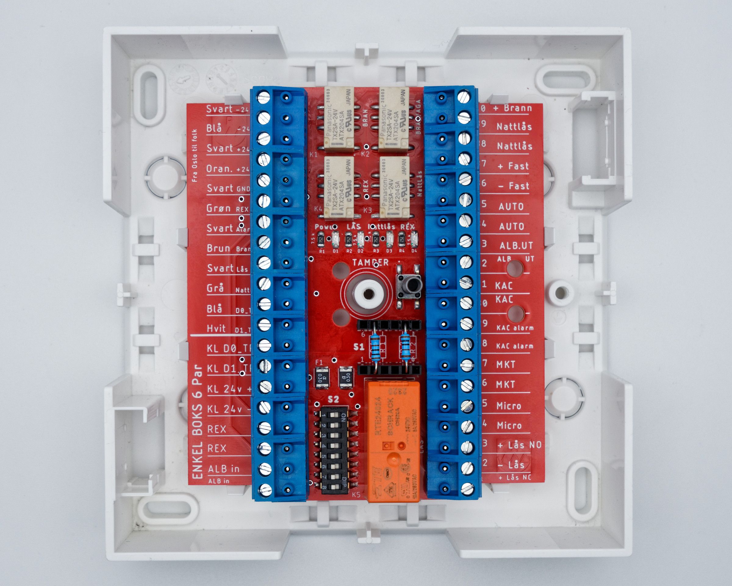
Enkel Boks 6 Par
NOK 1,200.00
Price excl. VAT. Linjator box not included.
2-year warranty.
Sold to business customers only.
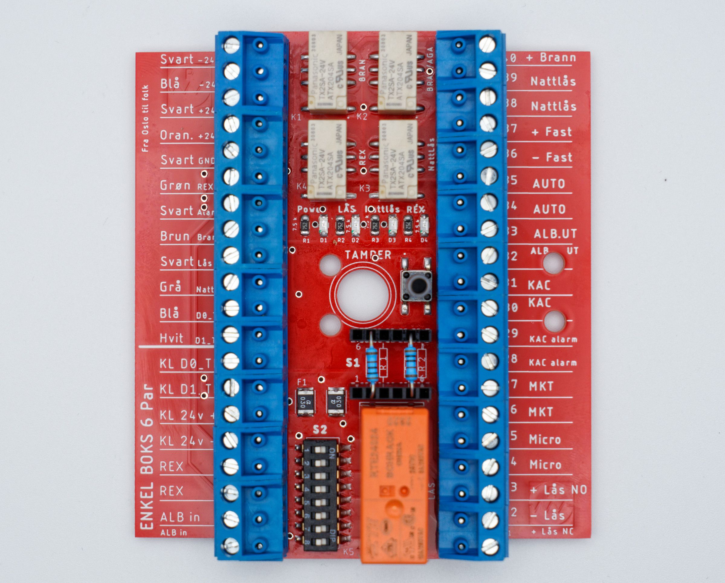
Enkel Boks 6 Par is a complete interface system that combines high functionality with simplified cabling. With just a 6-pair cable, the solution gives a more efficient and cost-saving installation without compromising performance. Using decentralised power supply also removes limitations linked to cable distance, which gives greater freedom and flexibility in the installation. The solution has been developed with regard to the requirements of TEK17 (the Norwegian building regulations) for doors and escape routes (including §11-13, §11-14 and §12-13), including fire override and correct configuration of the lock on an escape route.
Main features and benefits
- All signals from the access controller are used as control signals for the built-in relays in Enkel Boks 6 Par. This includes, among other things:
- Relay for fire alarm control
- Relay for night lock (NC)
- Relay for main lock control — a specialised relay with a capacity of 8 A is used here, which ensures reliable operation of locks. This relay is designed for long life, with an expected operating life of up to 25 years.
- A dedicated relay for the elbow switch input signal, which allows the elbow switch to be used at the same time both as a REX control signal for access control and as a signal for automatic door opening (AUTO).
- Adapted for use with decentralised power supply, with no practical limit on cable distance up to or over 100 metres.
- Simplified cable handling and fast installation with a reduced amount of cable.
📎 Documentation
Communication and connection
- Compatible with: Linjator 120140 / 120103
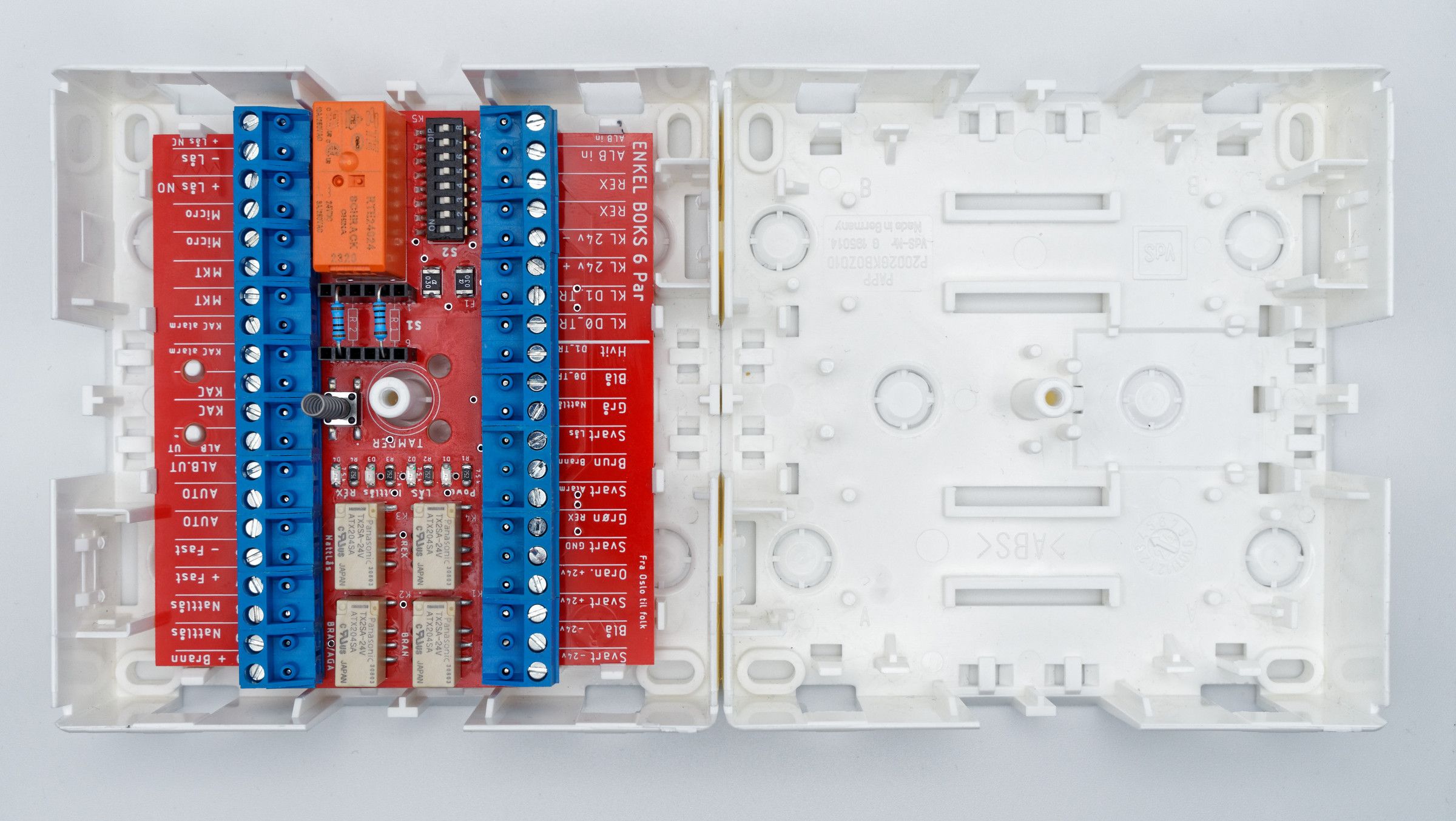
- Dimensions: 104 × 90 × 21 mm
- Cable: 6-pair (up to 100 m), standard colour code
- Power: 24 VDC ±10%, current consumption in idle mode 60 mA
- Maximum calculated current through the board’s tracks: up to 5 A
- Inputs/outputs: 40 easily removable connectors for wiring
- FIRE input (dry contact/24 V) with application priority over night/standard
- DIP jumpers for local configuration
Signals from the ACS
- Power supply to the reader 24 V
- Reader control via OSDP, Wiegand or RS-485
- Night lock control (NC)
- Constant 24 V auxiliary voltage
- Fire-controlled 24 V (release on FIRE)
- KAC (green break-glass emergency release at the door) and tamper
- Door status (alarm)
- Main lock control NO/NC 24 V
The lock type is selected by terminal: fail-safe lock (unlocked without power) on terminal 21, fail-secure lock (locked without power) on terminal 23, 0 V on terminal 22. On doors on an escape route, the lock must be fail-safe (terminal 21). - REX, elbow switch
Door components
- Power supply to the electromagnet that holds the door open (HOLD)
- Night lock power supply
- Night lock control
- Signal from the external elbow switch (mounted 0.8–1.2 m above the floor and outside the swing area of the door leaf)
- Signal from the internal elbow switch (mounted 0.8–1.2 m above the floor and outside the swing area of the door leaf)
- Signal from REX (mounted outside the swing area of the door leaf)
- Alarm KAC signal (green break-glass emergency release at the door)
- Signal for activating the emergency release of the door (KAC)
- Door magnetic contact signal
- Door microswitch signal
- Lock control NO/NC 24 V
- Automatic door operator control (AUTO)
Power supply
Constant power supply (always active):
- Night lock – two wiring methods:
• Doors that must be unlocked in a fire (e.g. interior corridor doors): constant 24 V on terminal 37. On FIRE the night lock receives a command via the control loop 38–39 and retracts the bolt.
• Doors that must remain locked in a fire (e.g. exterior doors): the night lock is supplied from fire-controlled 24 V (terminal 40). On FIRE the power is cut, the night lock stays locked, and the door is opened mechanically when needed. - Backlighting: 24 V for readers, illumination of KAC, indicators and elbow switch (max. 300 mA)
Fire-controlled power supply (overrides all modes):
- Electromagnet (HOLD) is disconnected on FIRE
- Main lock 24 V is disconnected (fail-safe opening on an escape route)
- Night lock is deactivated/disconnected on an escape route
- FIRE overrides the lock on an escape route: power is disconnected for fail-safe opening; night is overridden
Functional operating modes
Standard mode — door locked:
- Reader: access granted → the door unlocks → manual opening, or automatic opening with the outdoor elbow switch. If needed, automatic opening on access can be wired via terminals 33 and 35 – the door then also opens automatically in a fire and stays open as long as it is unlocked. This is for sites where the function is needed and the fire functions are not used.
- Press REX → the door unlocks → manual opening
- Elbow switch (secure side) → automatic opening
- Manual opening without authorisation → door intrusion alarm (does not prevent exit on an escape route)
- The night lock is deactivated automatically at each activation of the main lock
Door unlocked:
- Manual opening available
- Elbow switch → automatic opening
- Night lock deactivated
FIRE evacuation mode — escape door (inside and outside):
- Door unlocked (fail-safe)
- Hold-open magnet (HOLD) released
- Night lock overridden/deactivated
- Elbow switches active on both sides
- Manual opening available
(Re-entry must be possible — no “electronic dead end”)
Technical note: To meet TEK17, the lock on an escape route must be fail-safe and wired to terminals 21 and 22.
Safety and reliability
- Short-circuit protection: 300 mA fuses (auxiliary circuits), electrically isolated from the main power supply to the lock
- Tamper monitoring: signal on unauthorised access to the box
Installation and operation
- Choose a suitable position for the box on the inside (protected side) of the door to prevent unauthorised access.
- Mount the box securely on a wall or other suitable place that protects against mechanical damage.
- Connect the box to the ACS controller with a 6-pair cable.
- Adjust the cable length and ensure the correct colour coding.
- Adjust the DIP jumpers according to the requirements of the site. On doors on an escape route, the lock must be wired as fail-safe (terminal 21).
- Connect all necessary signals and power connections to the box. Connect the FIRE input (dry contact/24 V) and make sure that FIRE overrides night/standard.
- Check all signals using test mode (indication on the circuit board). Test the FIRE function, re-entry and lock opening in particular.
- Close the box and carry out a final test. Document the DIP settings and test results in the FDV documentation (operation and maintenance documentation).
Request a quote
Enquiries by email or phone: info@teren.no · +47 400 72 382
Sold to business customers only.