Enkel Boks + Avigilon Alta
Wiring diagrams for Enkel Boks and Avigilon Alta Core and Alta SDC, with the controller in the central cabinet and one 6-pair cable to the door.
Avigilon Alta Core – Smart Hub in the central cabinet
The Avigilon Alta Core Series Smart Hub (8-Port Board OP-EX-8E; the 4-Port OP-EX-4E is wired the same way) sits in the central cabinet on its own FPV power supply, while Enkel Boks has its own 24 V power supply; one 6-pair cable with all 12 conductors runs to the door. RELAY 2 is a dry NO contact to terminal 9, the night lock is controlled by the time relay, and the Avigilon Smart Reader sits on 13–16 with RS-485 through pair 6 and 24 V from the box. A black conductor from READER 2 GND to the box's 0 V is the required common 0 V.
Download wiring diagram (in Norwegian): Avigilon Alta Core – Smart Hub in the central cabinet (PDF)
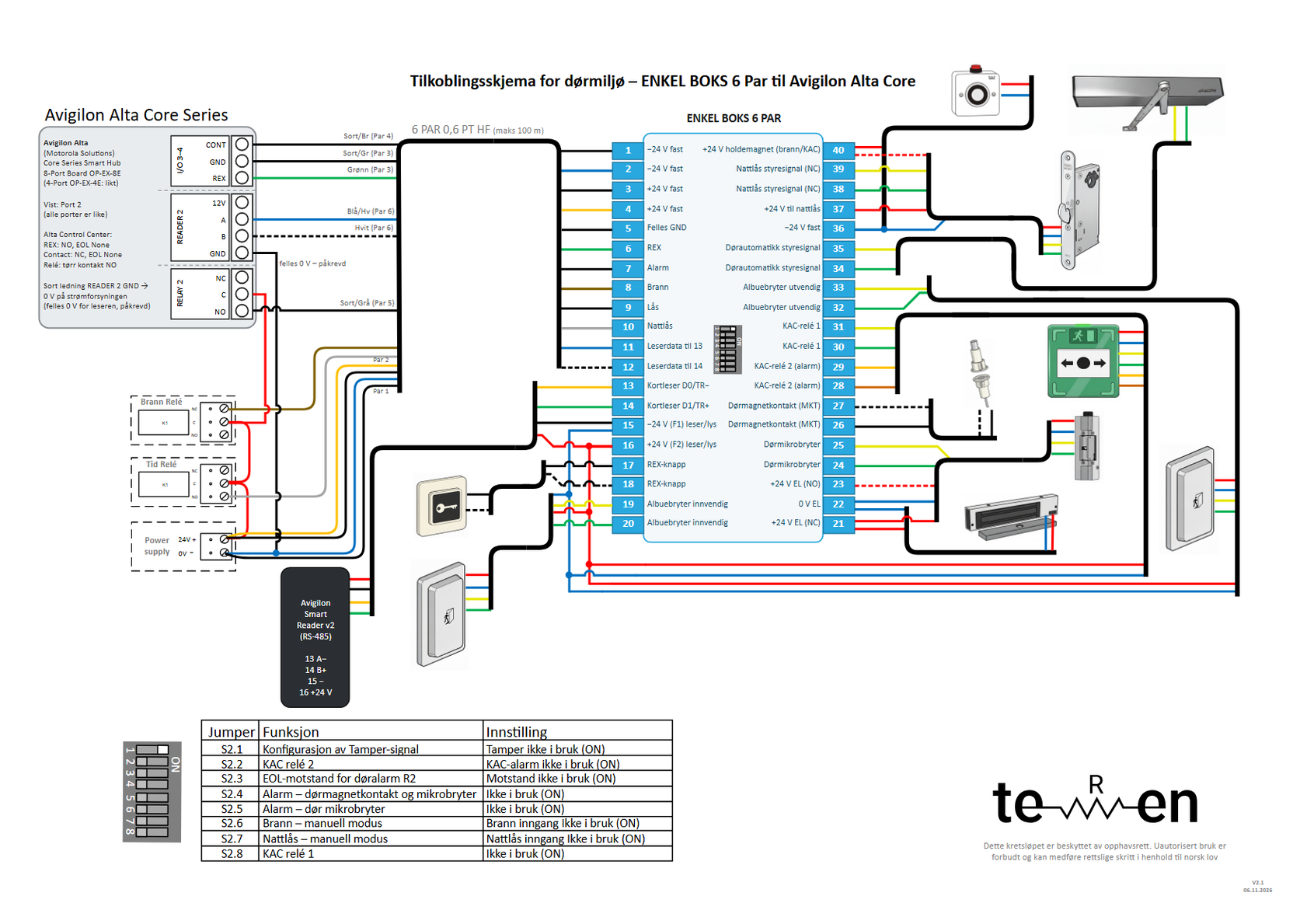
- Lock: OP-EX-8E RELAY 2 NO → terminal 9 (Black/grey, pair 5); RELAY 2 C gets +24 V from the power supply via time relay C and fire relay C.
- Inputs: 5 (Black/green, pair 3) → I/O 3–4 GND, 6 (Green, pair 3) → I/O 3–4 REX, 7 (Black/brown, pair 4) → I/O 3–4 CONT. Input type REX and Contact, EOL None.
- Reader bus: READER 2 A → terminal 11 → 13 (Avigilon −A), READER 2 B → 12 → 14 (+B).
- Reader: Avigilon Smart Reader (12–24 V DC) on 13–16; Smart Reader v2 draws 0.12 A at 24 V. READER 2 12V is not used.
- Common 0 V – required: OP-EX-8E READER 2 GND → 0 V on the box's power supply.
- Fire: fire relay NC → terminal 8, not via FPV FAI.
- Port 2 is shown; all ports (one port = one door) are wired the same way, each to its own Enkel Boks.
Connection table (cable journal)
Cables
- 6 PAR 0,6 PT HF (max 100 m): Central cabinet (Smart Hub, power supply, fire relay, time relay) ↔ Enkel Boks
- In the central cabinet: Bridges in the cabinet
- Reader at the door: Enkel Boks 13–16 ↔ Avigilon Smart Reader (RS-485 through pair 6)
One row = one conductor: terminal in Enkel Boks → conductor → where it goes. The tables are translated from the PDF, which is in Norwegian; the PDF is the document to install from.
| Terminal | Function | Conductor | Connects to | Note |
|---|---|---|---|---|
| 1 | −24 V constant | Black/blue (pair 1) | Power supply 0 V (−) | |
| 2 | −24 V constant | Blue (pair 1) | Power supply 0 V (−) | |
| 3 | +24 V constant | Black/or. (pair 2) | Power supply +24 V | |
| 4 | +24 V constant | Orange (pair 2) | Power supply +24 V | |
| 5 | GND to Avigilon | Black/green (pair 3) | OP-EX-8E I/O 3–4 GND | Common for REX (5–6) and door contact (7–5). |
| 6 | REX to Avigilon | Green (pair 3) | OP-EX-8E I/O 3–4 REX | Potential-free NO in Enkel Boks (5–6). Input type REX, EOL None. |
| 7 | Alarm (door status) | Black/brown (pair 4) | OP-EX-8E I/O 3–4 CONT | NC loop (closed = normal). Input type Contact, EOL None. |
| 8 | Fire | Brown (pair 4) | Fire relay NC (C = +24 V) | +24 V = normal. Fire: the voltage drops out. |
| 9 | Lock (open) | Black/grey (pair 5) | OP-EX-8E RELAY 2 NO | Dry relay output. RELAY 2 C gets +24 V from the power supply. |
| 10 | Night lock (central) | Grey (pair 5) | Time relay NO (C = +24 V) | +24 V = night mode. |
| 11 | Reader bus A− → 13 | Blue/white (pair 6) | OP-EX-8E READER 2 A | Straight through 11 → 13 in the box. Avigilon: −A. |
| 12 | Reader bus B+ → 14 | White (pair 6) | OP-EX-8E READER 2 B | Straight through 12 → 14 in the box. Avigilon: +B. |
| – | +24 V to lock relay | Red | Power supply +24 V (via time relay C and fire relay C) → OP-EX-8E RELAY 2 C | Like the COM bridge on Axis/RCO. |
| – | Common 0 V reader bus | Black | OP-EX-8E READER 2 GND → power supply 0 V | Required: Enkel Boks has its own 24 V power supply, so the reader (power from the box) and READER 2 must have common 0 V for RS-485. Marked «common 0 V – required» on the drawing. |
| 13 | Reader RS-485 A− | per reader | Avigilon Smart Reader A− (−A) | |
| 14 | Reader RS-485 B+ | per reader | Avigilon Smart Reader B+ (+B) | |
| 15 | Reader − | per reader | Avigilon Smart Reader GND | −24 V via F1 300 mA. |
| 16 | Reader + | per reader | Avigilon Smart Reader VIN (12–24 V DC) | +24 V via F2 300 mA. Smart Reader v2: 0.12 A at 24 V (guide p. 71). |
In the central
- Red bridge in the central cabinet: power supply +24 V → time relay C → fire relay C → OP-EX-8E RELAY 2 C.
- Black conductor from OP-EX-8E READER 2 GND to 0 V on the power supply (common 0 V for the reader), marked «common 0 V – required» on the drawing.
- READER 2 12V is not used: the reader gets 24 V from Enkel Boks 15–16.
- All 12 conductors in the 6-pair cable are in use: pair k goes to terminal 2k−1 (black/striped) and 2k (colour).
The door side (21–40 and 17–20) is the same for all brands – see the drawing, page 1.
Controller setup and DIP in Enkel Boks
| Setting | Factory | Used as | Status |
|---|---|---|---|
| Port 2 (one port = one door) | RELAY / READER / I/O (REX + CONT) per port | Port 2 shown; all ports are connected the same way | OK |
| RELAY 2 (NC/C/NO) | Dry relay output on 8-Port Board | NO → terminal 9, C = +24 V from the power supply. Load: coil K5 in Enkel Boks | OK |
| Relay rating | 5 A @ 24 V DC resistive (datasheet OP-EX-8E) | Drives only coil K5 in Enkel Boks: good margin | OK |
| I/O 3–4 REX | Input type REX; nominal 5 V DC, 1 kΩ (datasheet) – dry contact | REX from terminal 5–6 (NO), EOL None | OK |
| I/O 3–4 CONT | Input type Contact | Door status from terminal 7–5 (NC = door closed), EOL None | OK |
| EOL (Ports → Cable) | None / Cut Line / Line Shorted / Both (guide p. 50) | None: Enkel Boks has no EOL resistors | OK |
| READER 2 (RS-485, −A/+B) | Avigilon Smart Reader via RS-485 | Data via pair 6 (twisted pair), power from the box 15–16 | OK |
| Max reader bus length | Recommended max 91 m with CAT6 when power runs in one pair, 152 m with two power pairs (SDC guide p. 12) | The reader gets power from Enkel Boks 15–16, not over the cable. Only data runs in pair 6 (twisted pair): 100 m is below 152 m. Connect the screen (if the cable has one) to GND only at the controller end | OK |
| Power Smart Hub | FPV4/FPV6 24 V with fire alarm input (FAI) | Smart Hub on its own FPV; Enkel Boks on its own 24 V. Common 0 V via READER 2 GND → 0 V | OK |
| DIP | Function | Suggestion for this setup |
|---|---|---|
| S2.6 | Fire – manual mode | OFF when a fire relay is connected to terminal 8 |
| S2.7 | Night lock – manual mode | OFF when the night lock is controlled from terminal 10 |
| S2.8 | Emergency release, relay 1 (KAC) | OFF when an emergency release (KAC box) is connected to 30–31 |
Avigilon Alta SDC – controller in the central cabinet
The Avigilon Alta Single Door Controller (OP-CR-SDC) sits in the central cabinet and runs on the same 24 V power supply as Enkel Boks, so common 0 V follows automatically; one 6-pair cable with all 12 conductors runs to the door. Relay 1 is set to «dry» and is a dry NO contact to terminal 9, the night lock is controlled by the time relay, and the Avigilon Smart Reader sits on 13–16 with RS-485 through pair 6 and 24 V from the box.
Download wiring diagram (in Norwegian): Avigilon Alta SDC – controller in the central cabinet (PDF)
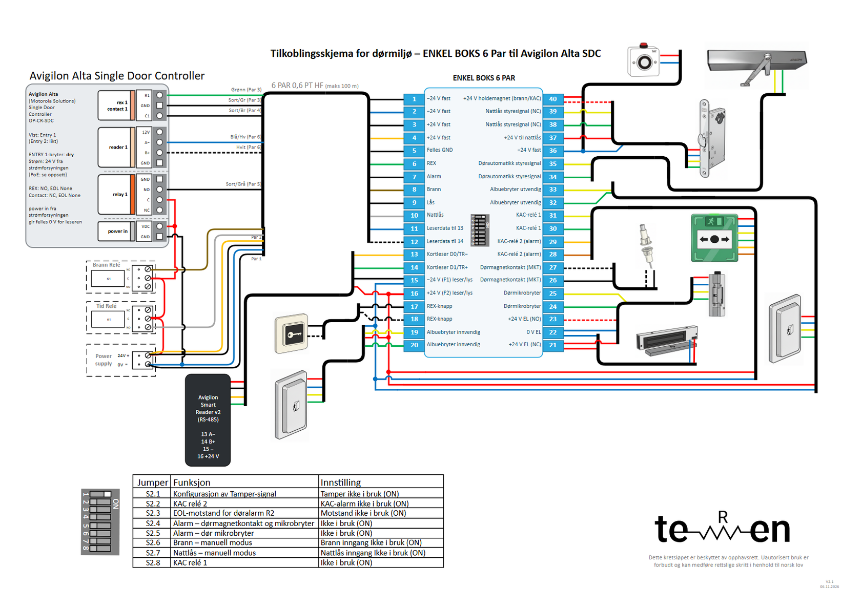
- Lock: SDC relay 1 NO → terminal 9 (Black/grey, pair 5); the ENTRY 1 switch on «dry» (not 24V wet), relay 1 C gets +24 V from the power supply. Switch off the SDC before the switch is moved.
- Inputs: 5 (Black/green, pair 3) → SDC rex 1/contact 1 GND (⏚), 6 (Green, pair 3) → R1, 7 (Black/brown, pair 4) → C1. EOL None.
- Reader bus: SDC reader 1 A− → terminal 11 → 13, B+ → 12 → 14.
- Reader: Avigilon Smart Reader (12–24 V DC) on 13–16, 0.12 A at 24 V (Smart Reader v2). reader 1 12V and GND are not used.
- Power: SDC power in VDC/GND from the power supply in the central cabinet (24 V).
- Only data runs in pair 6; Avigilon recommends max 91 m with CAT6 when power runs in one pair and 152 m with two power pairs, and 100 m is below 152 m.
- Entry 2 is wired the same way to a separate Enkel Boks.
Connection table (cable journal)
Cables
- 6 PAR 0,6 PT HF (max 100 m): Central cabinet (SDC, power supply, fire relay, time relay) ↔ Enkel Boks
- In the central cabinet: Power and bridges in the cabinet
- Reader at the door: Enkel Boks 13–16 ↔ Avigilon Smart Reader (RS-485 through pair 6)
One row = one conductor: terminal in Enkel Boks → conductor → where it goes. The tables are translated from the PDF, which is in Norwegian; the PDF is the document to install from.
| Terminal | Function | Conductor | Connects to | Note |
|---|---|---|---|---|
| 1 | −24 V constant | Black/blue (pair 1) | Power supply 0 V (−) | |
| 2 | −24 V constant | Blue (pair 1) | Power supply 0 V (−) | |
| 3 | +24 V constant | Black/or. (pair 2) | Power supply +24 V | |
| 4 | +24 V constant | Orange (pair 2) | Power supply +24 V | |
| 5 | GND to Avigilon | Black/green (pair 3) | SDC rex 1/contact 1 GND (⏚) | Common for REX (5–6) and door contact (7–5). |
| 6 | REX to Avigilon | Green (pair 3) | SDC rex 1/contact 1 R1 | Potential-free NO in Enkel Boks (5–6). EOL None. |
| 7 | Alarm (door status) | Black/brown (pair 4) | SDC rex 1/contact 1 C1 | NC loop (closed = normal). EOL None. |
| 8 | Fire | Brown (pair 4) | Fire relay NC (C = +24 V) | +24 V = normal. Fire: the voltage drops out. |
| 9 | Lock (open) | Black/grey (pair 5) | SDC relay 1 NO | ENTRY 1 switch on «dry». relay 1 C gets +24 V from the power supply. |
| 10 | Night lock (central) | Grey (pair 5) | Time relay NO (C = +24 V) | +24 V = night mode. |
| 11 | Reader bus A− → 13 | Blue/white (pair 6) | SDC reader 1 A− | Straight through 11 → 13 in the box. |
| 12 | Reader bus B+ → 14 | White (pair 6) | SDC reader 1 B+ | Straight through 12 → 14 in the box. |
| – | +24 V to lock relay | Red | Power supply +24 V (via time relay C and fire relay C) → SDC relay 1 C | Like the COM bridge on Axis/RCO. |
| – | +24 V power in | Red | Power supply +24 V → SDC power in VDC | The guide: 24 V @ 1.1 A (min) when the relays are to supply 24 V; with «dry» the SDC draws only its own current. |
| – | 0 V power in | Black | Power supply 0 V → SDC power in GND (⏚) | Also provides common 0 V for RS-485 to the reader. |
| 13 | Reader RS-485 A− | per reader | Avigilon Smart Reader A− (−A) | |
| 14 | Reader RS-485 B+ | per reader | Avigilon Smart Reader B+ (+B) | |
| 15 | Reader − | per reader | Avigilon Smart Reader GND | −24 V via F1 300 mA. |
| 16 | Reader + | per reader | Avigilon Smart Reader VIN (12–24 V DC) | +24 V via F2 300 mA. Smart Reader v2: 0.12 A at 24 V (guide p. 71). |
In the central
- Red bridge in the central cabinet: power supply +24 V → time relay C → fire relay C → SDC relay 1 C and power in VDC.
- Black conductor from 0 V on the power supply to SDC power in GND.
- reader 1 12V and GND are not used: the reader gets 24 V from Enkel Boks 15–16.
- All 12 conductors in the 6-pair cable are in use: pair k goes to terminal 2k−1 (black/striped) and 2k (colour).
The door side (21–40 and 17–20) is the same for all brands – see the drawing, page 1.
Controller setup and DIP in Enkel Boks
| Setting | Factory | Used as | Status |
|---|---|---|---|
| ENTRY 1 switch | Selects relay 1: 12V wet / dry / 24V wet (QSG p. 2) | «dry»: relay 1 NO/C as potential-free contact. Switch off SDC before the switch is moved | Must be changed |
| relay 1 (⏚/NO/C/NC) | With «dry»: NO/NC and C to external power | NO → terminal 9, C = +24 V from the power supply | OK |
| Relay rating | 2 A @ 24 V DC resistive (datasheet OP-CR-SDC) | Drives only coil K5 in Enkel Boks: good margin | OK |
| rex 1 / contact 1 (R1, ⏚, C1) | REX and door contact to ⏚ | R1 = REX from 5–6 (NO), C1 = door status from 7–5 (NC), EOL None | OK |
| reader 1 (12V, A−, B+, ⏚) | Avigilon Smart Reader via RS-485 | A−/B+ via pair 6, power from the box 15–16 | OK |
| power in (VDC, ⏚) | 12 V @ 2.2 A or 24 V @ 1.1 A (min); otherwise PoE | 24 V from the power supply in the central cabinet | OK |
| PoE (alternative) | SDC can run on PoE alone | With PoE: connect ⏚ (power in or reader 1) to 0 V on the power supply for common 0 V | OK |
| Max reader bus length | Recommended max 91 m with CAT6 when power runs in one pair, 152 m with two power pairs (installation guide p. 12) | The reader gets power from Enkel Boks 15–16, not over the cable. Only data runs in pair 6 (twisted pair): 100 m is below 152 m. Connect the screen (if the cable has one) to GND only at the controller end | OK |
| Entry 2 | relay 2, rex 2/contact 2, reader 2, wiegand 2 | The second door is connected the same way to its own Enkel Boks | OK |
| DIP | Function | Suggestion for this setup |
|---|---|---|
| S2.6 | Fire – manual mode | OFF when a fire relay is connected to terminal 8 |
| S2.7 | Night lock – manual mode | OFF when the night lock is controlled from terminal 10 |
| S2.8 | Emergency release, relay 1 (KAC) | OFF when an emergency release (KAC box) is connected to 30–31 |