Enkel Boks + generic controller
Wiring diagram for Enkel Boks and any access controller with one relay and two inputs: the starting point for a system that does not have its own diagram yet.
Generic controller – base diagram (controller in the central cabinet)
The base diagram shows a typical single-door access controller with one relay and two inputs, placed in the central cabinet together with two 24 V power supplies, fire relay and time relay. One 6-pair cable (max 100 m) with all 12 conductors runs to Enkel Boks: OUT 1 gives +24 V on terminal 9, IN 1 reads the door status loop and IN 2 reads REX, and the OSDP reader sits on 13–16 with 24 V from the box. Use the diagram when your system does not have its own Teren diagram; the door side (17–40) is the same on all 6 Par diagrams, while 13–16 are used differently (on SALTO and U-PROX the 12 V converter sits on 13–15).
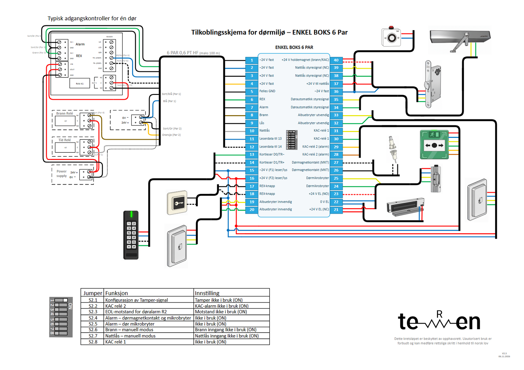
- Lock: controller OUT 1 NO → terminal 9 (Black/grey, pair 5). OUT 1 C gets voltage from the controller's VOUT: measure during installation that VOUT gives +24 V. If VOUT does not give +24 V, use the standard wiring: dry NO contact with C = +24 V from the power supply.
- Inputs: 5 (Black/green, pair 3) → controller GND (bridge GND at IN 1 ↔ GND at IN 2), 6 (Green, pair 3) → IN 2 (REX, NO), 7 (Black/brown, pair 4) → IN 1 (alarm/door status, NC).
- Fire: fire relay NC (C = +24 V) → terminal 8 (Brown, pair 4). Night lock: time relay NO (C = +24 V) → terminal 10 (Grey, pair 5).
- OSDP: controller READER TR+ → terminal 11 → 13 and TR- → 12 → 14, as drawn. Pair 6 is a pure pass-through, so the controller's TR+ must end on the reader's TR+.
- The reader on 13–16 gets 24 V from the box (F1/F2 300 mA) and must tolerate 12–24 V; a reader that only tolerates 12 V is connected directly from the controller.
- The diagram has two 24 V power supplies: «Power supply» (controller, fire relay and time relay) and the supply on pairs 1–2 to Enkel Boks. Common 0 V between them is required, because +24 V on terminals 8, 9 and 10 comes from «Power supply», and the reader gets data from the controller but power from the box. The drawing shows common 0 V only as a dotted line – connect it as a normal conductor, or use one power supply for everything.
- The controller must have a relay that can give +24 V on 9 and two inputs for dry contact (REX and door status).
Connection table (cable journal)
Cables
- 6 PAR 0,6 PT HF (max 100 m): Central cabinet (typical controller, power supply 24 V, fire relay, time relay) ↔ Enkel Boks
- In the central cabinet: Power and bridges between power supply, controller and relays
- Reader at the door: Enkel Boks 13–16 ↔ card reader with keypad (data through pair 6)
One row = one conductor: terminal in Enkel Boks → conductor → where it goes. The tables are translated from the PDF, which is in Norwegian; the PDF is the document to install from.
| Terminal | Function | Conductor | Connects to | Note |
|---|---|---|---|---|
| 1 | −24 V constant | Black/blue (Pair 1) | Power supply 0V − | The supply top right in the central cabinet (unnamed). |
| 2 | −24 V constant | Blue (Pair 1) | Power supply 0V − | |
| 3 | +24 V constant | Black/Or (Pair 2) | Power supply 24V + | |
| 4 | +24 V constant | Orange (Pair 2) | Power supply 24V + | |
| 5 | GND to controller | Black/Gr (Pair 3) | Controller GND (at IN 1) | Bridge GND ↔ GND (at IN 2) on the controller: common for alarm and REX. |
| 6 | REX to controller | Green (Pair 3) | Controller IN 2 (REX) | Potential-free contact 5–6 in Enkel Boks (REX button 17–18 or K4). NO. |
| 7 | Alarm | Black/Br (Pair 4) | Controller IN 1 (Alarm) | Loop 7 → tamper → emergency release/KAC 2 → MKT → microswitch → GND (5). Closed = normal. |
| 8 | Fire | Brown (Pair 4) | Fire relay NC (C = +24 V) | +24 V = normal. Fire: the voltage drops out. |
| 9 | Lock (open) | Black/Gr (Pair 5) | Controller OUT 1 NO (Relay K1) | OUT 1 C gets voltage from the controller's VOUT. Measure during installation that VOUT gives +24 V (coil K5). If VOUT does not give +24 V, use the standard connection: dry NO contact with C = +24 V from the power supply. |
| 10 | Night lock (central) | Grey (Pair 5) | Time relay NO (C = +24 V) | +24 V = night mode. |
| 11 | OSDP → 13 | Blue/Wh (Pair 6) | Controller READER TR+ (OSDP) | Straight through 11 → 13 (marked D0\TR−, just a name). Check during installation that the controller's TR+ reaches the reader's TR+ (follow the polarity through to the reader). |
| 12 | OSDP → 14 | White (Pair 6) | Controller READER TR- (OSDP) | Straight through 12 → 14 (marked D1\TR+, just a name). The controller's TR− must reach the reader's TR−. |
| – | +24 V to controller | Red | Power supply → controller VIN | Top screw on «Power supply» (24V +). |
| – | 0 V to controller | Black | Power supply → controller GND | Bottom screw on «Power supply» (0V −). |
| – | +24 V to relays | Red | Power supply → Time relay C → Fire relay C | Same terminal as VIN. |
| – | Voltage to lock relay | Red | Controller VOUT → OUT 1 C | |
| – | GND bridge | Black | Controller GND (IN 1) ↔ GND (IN 2) | |
| – | Common 0 V | Black (dotted) | Power supply (black terminal) ↔ power supply 0V − (pair 1) | Dotted line on the drawing, but required: common 0 V for fire (8), lock (9), night lock (10) and OSDP. Connect it as a normal conductor, or use one power supply for everything. |
| 13 | Reader data D0\TR− | Green | Card reader green | From 11 (TR+ on the controller). |
| 14 | Reader data D1\TR+ | White | Card reader white | From 12 (TR− on the controller). |
| 15 | Reader − | Blue | Card reader − | −24 V via F1 300 mA. |
| 16 | Reader + | Red | Card reader + | +24 V via F2 300 mA. Use a reader for 12–24 V; a reader that tolerates only 12 V is connected directly to the controller. |
In the central
- The controller sits in the central cabinet together with the power supply, fire relay and time relay. Only the card reader and the door equipment are at the door.
- All 12 conductors in the 6-pair cable are in use: pair k goes to terminal 2k−1 (black/striped) and 2k (colour).
- Two 24 V supplies are drawn: «Power supply» (controller and relays) and a supply without a name (pair 1–2). Common 0 V is only drawn as a dotted line, but is required: connect it as a normal conductor, or use one power supply for everything.
- Red bridge in the central cabinet: «Power supply» → time relay C → fire relay C; the same terminal goes to controller VIN.
The door side (13–40) in this base drawing is the reference for all brands – see the drawing, page 1.
Controller setup and DIP in Enkel Boks
| Setting | Factory | Used as | Status |
|---|---|---|---|
| IN 1 | Alarm (the drawing). No manual | Alarm loop from terminal 7 to GND (5). Closed = normal (NC), without EOL resistor (EOL in the R2 position, S2.3 OFF, only when the controller or the customer requires it) | OK |
| IN 2 | REX (the drawing). No manual | REX from terminal 6, potential-free NO contact | OK |
| OUT 1 (Relay K1) | Lock relay NO/C/NC (the drawing) | C from VOUT, NO to terminal 9. +24 V = open | OK |
| VOUT | Not stated | Measure during installation that VOUT gives +24 V against −24 V in Enkel Boks (coil K5 on terminal 9). If it does not: dry NO contact with C = +24 V from the power supply | OK |
| VIN / GND | 24 V from «Power supply» | Red → VIN (24V +), black → GND (0V −). | OK |
| READER TR+ / TR− | OSDP (RS-485) | Pair 6 to 11–12 → 13–14; check that the controller's TR+ reaches the reader's TR+. VO, LED and BZR are not used; the reader gets 24 V from 15–16 and must tolerate 12–24 V | OK |
| DIP | Function | Suggestion for this setup |
|---|---|---|
| S2.1–S2.5 | Tamper, emergency release/KAC relay 2, EOL, MKT, microswitch | ON (not in use) as in the table, OFF for functions that are connected |
| S2.6 | Fire – manual mode | OFF when a fire relay is connected to terminal 8 |
| S2.7 | Night lock – manual mode | OFF when the night lock is controlled from terminal 10 |
| S2.8 | Emergency release, relay 1 (KAC) | OFF when an emergency release (KAC box) is connected to 30–31 |