Enkel Boks + ICT
Wiring diagram for Enkel Boks and ICT Protege GX DIN-1D, with the controller in the central cabinet and one 6-pair cable to the door.
ICT Protege GX DIN-1D – controller in the central cabinet
The ICT Protege GX DIN Rail Single Door Controller (PRT-CTRL-DIN-1D) sits in the central cabinet on its own ICT 12 V power supply with battery, and one 6-pair cable with all 12 conductors runs to Enkel Boks. RELAY 1 is a dry NO contact to terminal 9, the night lock is controlled by the time relay (the controller has only one relay), and the OSDP reader sits on 13–16 with data through pair 6. Common 0 V from Protege GX S− to the box's power supply is required.
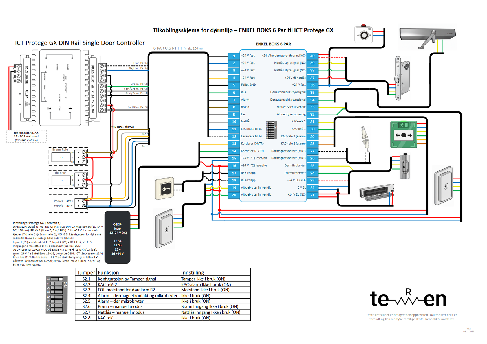
- Lock: Protege GX RELAY 1 NO → terminal 9 (Black/grey, pair 5); RELAY 1 C gets +24 V via time relay C and fire relay C. RELAY 1 must be selected as the lock output for the door in Protege GX.
- Inputs: 5 (Black/green, pair 3) → Protege GX V−, 6 (Green, pair 3) → Z2 (Input 2, REX), 7 (Black/brown, pair 4) → Z1 (Input 1, door contact). Both inputs on «No Resistor».
- Reader bus: SA → terminal 11 → 13, SB → 12 → 14. ICT requires screened cable (Belden 9842 or 24 AWG 120 Ω); Teren has approved unscreened pair 6 up to 100 m. Port type OSDP in Protege GX.
- The reader on 13–16 is an OSDP reader for 12–24 V DC; ICT tSec (9.5–14 V) does not tolerate 24 V from the box.
- Power: ICT PRT-PSU-DIN-5A 12 V DC → N+/N− (11–14 V DC). Never 24 V on N+.
- Common 0 V – required: black conductor Protege GX S− → 0 V on the power supply for Enkel Boks.
- Night lock: time relay NO → Grey (pair 5) → terminal 10.
Connection table (cable journal)
Cables
- 6 PAR 0,6 PT HF (max 100 m): Central cabinet (Protege GX, power supplies, fire relay, time relay) ↔ Enkel Boks
- In the central cabinet: Power, bridges and common 0 V in the cabinet
- Reader at the door: Enkel Boks 13–16 ↔ OSDP reader for 12–24 V DC (data through pair 6)
One row = one conductor: terminal in Enkel Boks → conductor → where it goes. The tables are translated from the PDF, which is in Norwegian; the PDF is the document to install from.
| Terminal | Function | Conductor | Connects to | Note |
|---|---|---|---|---|
| 1 | −24 V constant | Black/blue (pair 1) | Power supply 0 V (−) | |
| 2 | −24 V constant | Blue (pair 1) | Power supply 0 V (−) | |
| 3 | +24 V constant | Black/or. (pair 2) | Power supply +24 V | |
| 4 | +24 V constant | Orange (pair 2) | Power supply +24 V | |
| 5 | Common to Protege | Black/green (pair 3) | Protege GX V− (common for Z1/Z2) | Common for REX (5–6) and door contact (7–5). |
| 6 | REX to Protege | Green (pair 3) | Protege GX Z2 (Input 2, REX) | Potential-free NO in Enkel Boks (5–6). Input on «No Resistor». |
| 7 | Alarm (door status) | Black/brown (pair 4) | Protege GX Z1 (Input 1, door contact) | NC loop 7–5 (closed = door closed). Input on «No Resistor». |
| 8 | Fire | Brown (pair 4) | Fire relay NC (C = +24 V via time relay C) | +24 V = normal. Fire: the voltage drops out. |
| 9 | Lock (open) | Black/grey (pair 5) | Protege GX RELAY 1 NO | Dry contact. RELAY 1 C gets +24 V via time relay C and fire relay C. |
| 10 | Night lock (central) | Grey (pair 5) | Time relay NO (C = +24 V) | +24 V = night mode. Protege GX DIN-1D has only one relay. |
| 11 | Reader bus SA → 13 | Blue/white (pair 6) | Protege GX SA (RS-485 reader port) | Straight through 11 → 13 «D0\TR−» (SA = A). |
| 12 | Reader bus SB → 14 | White (pair 6) | Protege GX SB (RS-485 reader port) | Straight through 12 → 14 «D1\TR+». Unscreened twisted pair instead of ICT's screened cable: approved, max 100 m. |
| – | +24 V to time relay C | Red | Power supply +24 V → Time relay C | Start of the red chain: time relay C → fire relay C → the controller. |
| – | +24 V to lock relay | Red | Power supply +24 V (via time relay C and fire relay C) → Protege GX RELAY 1 C | Red chain as on the other Teren drawings. |
| – | Common 0 V – required | Black | Protege GX S− → power supply 0 V (Enkel Boks) | The reader gets power from the box and data from Protege: two power supplies, so common 0 V is required. |
| – | +12 V power in | Red | ICT PRT-PSU-DIN-5A 12 V + → Protege GX N+ | 11–14 V DC, 120 mA typical (p. 33). Never 24 V on N+. |
| – | 0 V power in | Black | ICT PRT-PSU-DIN-5A 0 V → Protege GX N− | 12 V DC 5 A, 110–240 V AC in, with battery (p. 10). |
| 13 | Reader RS-485 SA | per reader | OSDP reader A (RS-485) | Colour code per the reader. |
| 14 | Reader RS-485 SB | per reader | OSDP reader B (RS-485) | |
| 15 | Reader − | per reader | OSDP reader 0 V | −24 V via F1 300 mA. |
| 16 | Reader + | per reader | OSDP reader + (12–24 V DC) | +24 V via F2 300 mA. Only a reader for 12–24 V; ICT tSec (9.5–14 V) does not tolerate 24 V. |
In the central
- Red chain: power supply +24 V → time relay C → fire relay C → Protege GX RELAY 1 C.
- Protege GX runs on its own ICT power supply PRT-PSU-DIN-5A (12 V DC) with battery (N+/N−). Never 24 V on N+.
- Black conductor Protege GX S− → 0 V on the power supply for Enkel Boks: common 0 V – required.
- All 12 conductors in the 6-pair cable are in use: pair k goes to terminal 2k−1 (black/striped) and 2k (colour).
The door side (17–40) is the same as the base drawing – see the drawing, page 1.
Controller setup and DIP in Enkel Boks
| Setting | Factory | Used as | Status |
|---|---|---|---|
| N+ / N− (power) | 12 V DC, 11–14 V, 120 mA typical; no internal regulation (p. 10, 33) | ICT PRT-PSU-DIN-5A (12 V DC 5 A) with battery in the central cabinet | OK |
| RELAY 1 (NC / C / NO) | Form C, 7 A N.O./N.C. at 30 V AC/DC (pp. 23, 33) | NO → terminal 9, C = +24 V via time relay C and fire relay C. The load is only coil K5 in Enkel Boks | OK |
| Lock output for the door | Not set from the factory: the lock output for the door must be set to RELAY 1 (p. 18) | Select RELAY 1 (CP001:03) as the lock output for the door in Protege GX | Must be changed |
| Built-in reader | Off from the factory; address is set in Protege GX, port type ICT 485 or OSDP (p. 19) | Switch on, give a free address, port type OSDP (ICT AN-254 / AN-321) | Must be changed |
| Z1 (Input 1) / Z2 (Input 2), V− | Input 1 = door contact, Input 2 = REX; factory: EOL resistor required (pp. 18–20) | Z1 ← 7, Z2 ← 6, V− ← 5. Set both to «No Resistor» | Must be changed |
| SA / SB, S− / S+ (reader port) | RS-485, 12 V DC out on S−/S+; screened cable, Belden 9842 or 24 AWG 120 Ω (pp. 16–17) | SA → 11 → 13, SB → 12 → 14. Unscreened pair 6 approved, max 100 m. S+ not used, S− = common 0 V | OK |
| Reader on 24 V | ICT tSec readers: 12 V DC (9.5–14 V), 254 mA peak (ICT tSec Standard) — do not tolerate 24 V | OSDP reader for 12–24 V DC on 13–16. The reader's current at 24 V is added to the F1/F2 budget (max 300 mA) | OK |
| NA / NB, Ethernet | RS-485 module network (330 Ω at both ends), Ethernet to the Protege GX server (pp. 13–15) | Not drawn | OK |
| Diode across the lock | The manual shows a diode across the 12 V lock (p. 18) | No diode: RELAY 1 controls only the coil K5 in Enkel Boks | OK |
| DIP | Function | Suggestion for this setup |
|---|---|---|
| S2.1 | Tamper | ON (tamper in the box not connected) |
| S2.2 | Emergency release, relay 2 (KAC) | OFF when an emergency release (KAC box) is connected to 28–29 (logged as «door open») |
| S2.3 | EOL resistor R2 | ON (Z1 on «No Resistor», no R2) |
| S2.4 | Magnetic door contact and microswitch | OFF when MKT is connected to 26–27 |
| S2.5 | Door microswitch | OFF when a microswitch is connected to 24–25 |
| S2.6 | Fire – manual mode | OFF when a fire relay is connected to terminal 8 |
| S2.7 | Night lock – manual mode | OFF when the night lock is controlled from terminal 10 |
| S2.8 | Emergency release, relay 1 (KAC) | OFF when an emergency release (KAC box) is connected to 30–31; ON without an emergency release |