Enkel Boks + RCO
Wiring diagram for Enkel Boks and RCO R-CARD M5 DB-50 Gen2, with the door controller in the central cabinet and one 6-pair cable to the door.
RCO R-CARD M5 DB-50 Gen2 – controller in the central cabinet
The RCO R-CARD M5 DB-50 Gen2 sits in the central cabinet, and one 6-pair cable with all 12 conductors runs to Enkel Boks. DOOR RELAY (jumper P8 changed to potential-free NO) gives +24 V on terminal 9, the night lock is controlled by the time relay in the central cabinet, and the RCO reader sits on 13–16 with RS-485 through pair 6 and 24 V from the box. The DB-50 gets power and bus from the UC-50 Gen2, which runs on the same power supply as Enkel Boks.
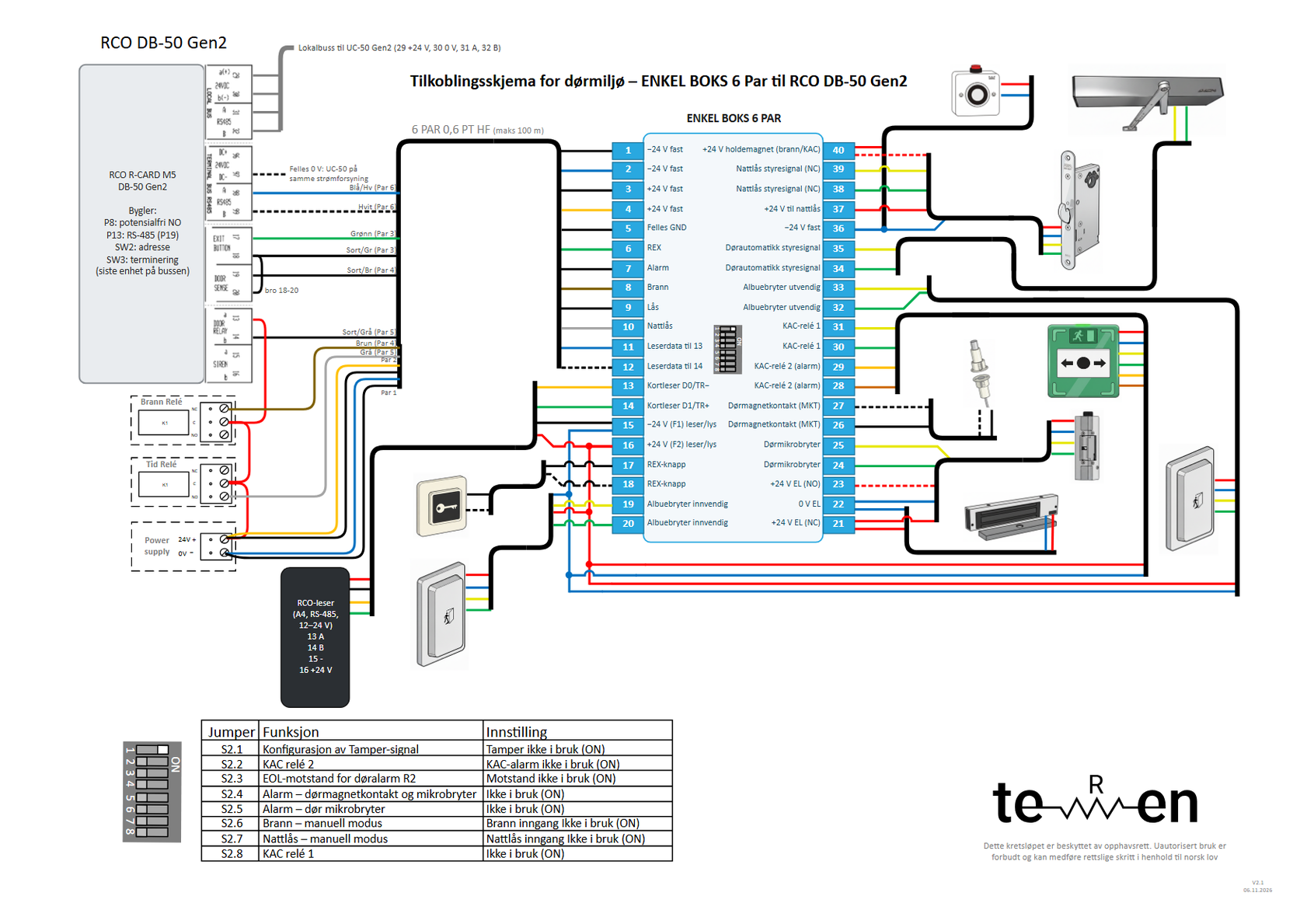
- Lock: DB-50 P4/14 DOOR RELAY b → terminal 9 (Black/grey, pair 5); P4/13 a gets +24 V from the power supply via time relay C and fire relay C (red chain). Jumper P8 is changed from «Matande NO» (factory) to potential-free NO.
- Inputs: 5 (Black/green, pair 3) → DB-50 P5/18 (+5 V) with bridge P5/18 ↔ P5/20; 6 (Green, pair 3) → P5/17 EXIT BUTTON (NO); 7 (Black/brown, pair 4) → P5/19 DOOR SENSE (NC = door closed). Unbalanced.
- Reader bus: P19/98 RS485 A → terminal 11 → 13, P19/99 RS485 B → 12 → 14; jumper P13 = RS-485 (P19). Max 100 m through pair 6.
- Reader: RCO reader for 12–24 V on 13–16 with 24 V from the box; the model is chosen per site.
- Power: the DB-50 gets 18–30 V DC from the local bus (P7) from the UC-50 Gen2. The UC-50 runs on the same power supply as Enkel Boks, so common 0 V follows from a single power supply.
- Night lock: time relay NO → Grey (pair 5) → terminal 10.
- DOOR RELAY tolerates max 1 A at 24 V DC and controls only the coil in the box.
Connection table (cable journal)
Cables
- 6 PAR 0,6 PT HF (max 100 m): Central cabinet (DB-50 Gen2, power supply, fire relay, time relay) ↔ Enkel Boks
- In the central cabinet: Bridges and RCO bus in the cabinet
- Reader at the door: Enkel Boks 13–16 ↔ RCO reader (RS-485 terminal bus, through pair 6)
One row = one conductor: terminal in Enkel Boks → conductor → where it goes. The tables are translated from the PDF, which is in Norwegian; the PDF is the document to install from.
| Terminal | Function | Conductor | Connects to | Note |
|---|---|---|---|---|
| 1 | −24 V constant | Black/blue (pair 1) | Power supply 0 V (−) | |
| 2 | −24 V constant | Blue (pair 1) | Power supply 0 V (−) | |
| 3 | +24 V constant | Black/or. (pair 2) | Power supply +24 V | |
| 4 | +24 V constant | Orange (pair 2) | Power supply +24 V | |
| 5 | Common to RCO | Black/green (pair 3) | DB-50 P5/18 (EXIT BUTTON, +5 V) | Bridge P5/18 ↔ P5/20 on DB-50: same common point for REX and door status. |
| 6 | REX to RCO | Green (pair 3) | DB-50 P5/17 EXIT BUTTON | Factory: NO, unbalanced. Potential-free contact in Enkel Boks (5–6). |
| 7 | Alarm (door status) | Black/brown (pair 4) | DB-50 P5/19 DOOR SENSE | Factory: NC = door closed, unbalanced. |
| 8 | Fire | Brown (pair 4) | Fire relay NC (C = +24 V) | +24 V = normal. Fire: the voltage drops out. |
| 9 | Lock (open) | Black/grey (pair 5) | DB-50 P4/14 DOOR RELAY b | Jumper P8 is changed from «Matande NO» (factory) to potential-free NO. P4/13 a gets +24 V from the power supply via time relay C and fire relay C. |
| 10 | Night lock (central) | Grey (pair 5) | Time relay NO (C = +24 V) | +24 V = night mode. Alternative: DB-50 SIREN P4/16 (see setup). |
| 11 | Reader bus A → 13 | Blue/white (pair 6) | DB-50 P19/98 RS485 A | Straight through 11 → 13 in the box. Jumper P13 = RS-485 (P19). |
| 12 | Reader bus B → 14 | White (pair 6) | DB-50 P19/99 RS485 B | Straight through 12 → 14 in the box. |
| – | +24 V to lock relay | Red | Power supply +24 V (via time relay C and fire relay C) → DB-50 P4/13 a | Red chain: power supply +24 V → time relay C → fire relay C → P4/13. |
| – | Common 0 V reader bus | Black | Power supply 0 V → DB-50 P19/97 (24VDC −) | Dashed stub on the drawing, marked «Common 0 V: UC-50 on the same power supply». UC-50 is on the same power supply as Enkel Boks, so common 0 V follows from one power supply. If UC-50 gets its own power supply, connect P19/97 to 0 V on the box's power supply with a solid conductor «common 0 V – required». |
| – | Local bus from UC-50 | RCO cable | DB-50 P7: 29 a(+), 30 b(−), 31 A, 32 B | Power 18–30 V and RS-485 from UC-50 Gen2 P2/5–8. SW2 = address, SW3 = termination on the last unit. |
| 13 | Reader RS485 A | per reader | RCO reader A | |
| 14 | Reader RS485 B | per reader | RCO reader B | |
| 15 | Reader − | per reader | RCO reader 24 V − | −24 V via F1 300 mA. |
| 16 | Reader + | per reader | RCO reader 24 V + | +24 V via F2 300 mA. Only an RCO reader for 12–24 V. |
In the central
- Red bridge in the central cabinet: power supply +24 V → time relay C → fire relay C → DB-50 P4/13.
- All 12 conductors in the 6-pair cable are in use: pair k goes to terminal 2k−1 (black/striped) and 2k (colour), as on the Axis drawing.
The door side (21–40 and 17–20) is the same for all brands – see the drawing, page 1.
Controller setup and DIP in Enkel Boks
| Setting | Factory | Used as | Status |
|---|---|---|---|
| P8 DOOR RELAY | Powered NO (outputs DB-50 voltage) | Potential-free NO, +24 V from the power supply in on 13 | Must be changed |
| P13 terminal bus | RS-485 (P19) – listed as supplied in the guide | Reader via pair 6 to the door. RS-485 to the reader through pair 6: max 100 m | OK |
| EXIT BUTTON 17–18 | NO, unbalanced, requires a potential-free contact | REX from terminal 5–6 | OK |
| DOOR SENSE 19–20 | NC = door closed, unbalanced | Alarm from terminal 7–5 | OK |
| SIREN 15–16 (optional) | Powered NO, common alarm | Individual night lock: P11 potential-free NO + «Day/night locking» in R-CARD M5 | Must be changed |
| Relay | Max 1 A at 24 V DC (PTC 1 A) | Drives coils in Enkel Boks | OK |
| Power | 18–30 V DC from the local bus (PTC 500 mA) | From UC-50 Gen2 | OK |
| DIP | Function | Suggestion for this setup |
|---|---|---|
| S2.6 | Fire – manual mode | OFF when a fire relay is connected to terminal 8 |
| S2.7 | Night lock – manual mode | OFF when the night lock is controlled from terminal 10 |
| S2.8 | Emergency release, relay 1 (KAC) | OFF when an emergency release (KAC box) is connected to 30–31 |